The J-STD-001 is a standardised and industry recognised modular training program that provides both theory and practical solder training for the electronics industries. Each module requires about 8 hours to complete. Depending the company requirements, the course can be taught using either tin/lead or lead-free solder.
IPC Pre-course (mandatory)
IPC Essentials:
- The IPC Essentials training module covers the essential features of the electronics industry, including its history, the development and practical application of standards, and the importance of certification to you and your company. This 2-hour, online course is divided into 5 sections and includes interactive quizzes to help you master concepts and assess your progress.
IPC Enhanced policies and procedures:
- The Enhanced Policy and Procedures training module provides an overview of the Policies and Procedures that govern IPC Professional Training and Certification. This module covers restrictions, recertification, testing, and other important information contained in revision 6 of the IPC Policies and Procedures document. It also includes instructions on how to access and use the IPC Online Certification Portal.
Module 1 – Introduction, J-STD-001 Overview (mandatory) –
The topics covered in this module are:
- Introduction
- General Requirements
- Applicable Documents
- Material, Components and Equipment Requirements
- General Soldering and Assembly Requirements
- Cleaning Process Requirements
- Staking, coatings and encapsulant requirements
Module 2 – Wires and Terminals (optional)
The topics covered in this module are:
- Wire and Cable Preparation
- Terminal installation and damage
- Mounting to terminals
- Soldering to terminals
The following types of terminals are covered theoretically and practically:
- Bifurcated Terminals
- Turret Terminals
- Slotted Terminals (theory only)
- Hook Terminals
- Pierced or Perforated Terminals
- Cup & Hollow Cylindrical Terminals
Module 3 – Through-Hole Mounting and Terminations (optional)
The topics covered in this module are:
- Lead prep
- Lead damage
- Lead protrusion, solder criteria
- Supported holes
- Unsupported holes
- Intrusive soldering (pin in paste)
Module 4 – Surface Mounting of Components (optional)
The topics covered in this module are:
- Lead Prep
- Mounting Requirements
- Process Considerations
- Solder Fillet Requirements
The following termination styles are covered in theory:
- Bottom Only Terminations
- Chip Components (1, 3 or 5 Sided Terminations)
- Cylindrical End Cap Terminations (MELF)
- Castellated Terminations
- Gull Wing Leads
- Round or Flattened Leads
- “J” Leads
- Butt Connections
- Flat Lug Leads
- Tall Profile Components W/Bottom only Terminations
- Inward Formed L-Shaped Ribbon Leads
- Surface Mount Area Array Packages (BGA)
- Quad Flat Pack (No Leads) QFNL, PQFN, Micro-lead frame
- Components with Bottom Thermal Plane Terminations (D-PAK®)
Module 5 – Inspection Methodology (optional)
The topics covered in this module are:
- Hardware Defects Requiring Disposition
- Inspection Methodology
- Process Control Requirements
- Statistical Process Control
- Wire and Terminal Requirements
- Through-Hole Requirements
- SMT Requirements
- PCB Requirements
- Conformal Coating and Encapsulation Requirements
Module 6 – Space Addendum (optional) (Pre-requisite - Module 1 PLUS at least 1 of the workmanship modules)
- Extra requirements for assembly in extreme environment
There is a theory exam at the end of each module. In addition, there are practical workmanship exams at the end of each of the optional modules 2, 3 and 4. On the next page are details of the workmanship board that the students complete if they are doing modules 3 and/or 4. At the end of module 5 there is a practical assessment of defects on populated boards provided. If modules 1, 2, 3 and 4 are all completed, then the theory side of module 5 is deemed to have been successfully completed and only the practical assessment is required.
J-STD-001 Workmanship Board
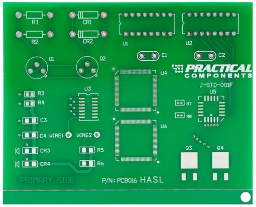
Through Hole Components Surface Mount Components
R1, R2 – 1/4 Watt Resistor R3, R4 – 0805 Resistor
CR1, CR2 – Diode C3, C4 – 1206 Capacitor
U1, U2 – 16 Pin DIP CR3, CR4 – 1206 MELF Diode
Q1, Q2 – Transistor with Spacer R5, R6 – 1206 Resistor (practice only)
C1, C2 – Radial Cap with Spacer U3 – 14 Pin SOIC
U4 – 100 Pin QFP
U5 – 20 Pin PLCC (J-Lead)
U6 – spare 100 pin QFP
Q3, Q4 – DPAK
R7, R8 – 0402 resistor
Wires
Wire 1, 2 - 22 AWG Wire
Terminals
Provide 2 examples for marking of each of the following:
Turret, bifurcated, solder cup and pierced and/or hook
|